|
All of the connecting pieces had to join to the sides of the horizontal pipes and therefore their ends needed to have the corresponding shape to form a perfect junction. The only way of doing this would be to drill through the pipe, but this would have to be done at the precise lengths required, with both ends drilled at the same angle. Fat chance of me accomplishing that with my limited equipment! My only recourse was to hacksaw all the pieces which just resulted in them having square ends. This meant that the direct contact between the pieces would be reduced to just where the edges met, resulting in gaps above and below the connection, as well as creating a weaker structure. As my model was purely for display and wouldn't be subjected to any excessive stress, it would still be sufficiently strong enough, so my only worry was filling all the gaps. The answer was to build the frame in two stages. The first was the basic assembly, using solder paint and then to go in and resolder every join with plenty of solid solder to fill the gaps. When this was done I used a knife, a file and plenty of wet & dry sandpaper to remove the excess solder and create the nice perfect joins I wanted. To actually stick all this brass together I used Carrs Solder and a Supercub Mini Blowtorch, bought from my local model railway shop. The process is fairly simple but the trick is not to heat everything up too much because it all starts to fall to pieces again. (Good news if you make a mistake though!) Of course I should point out that the brass pipe I was using was very thick walled (in fact almost solid) and the small diameter brass was fully solid rod. If the pipe had been thin walled this technique would not have worked because the solder would have just disappeared down the insides of the tubes. Then again, if it had been thin walled, I might have been able to shape the ends and do away with this proces.. Work continued for some time as there are over 300 pieces in the basic structure alone. The large main frame was built in the same way as the mid-sections except that the four longer lengths needed to have a third plastic spacer in the middle to keep everything lined up. When it was complete this spacer could just be cut up and removed. On the original model it appears as if the main frame and the two mid-sections are bolted together with sixteen metal clips. On my model, I soldered it all together so that it was nice and solid and the clips were the last details to be added to it, each just being made from plastic. Once the framework was completed, I had to paint it, which was a little unusual because you don't normally have to think about painting until near the end and here I was, having to choose my colour with only part of a model. Of course, white seems to be a simple colour, however there are quite a few different spray paints around and I had heard a story that the models should be painted matt white. Personally, I don't like matt paint, so I went with a gloss paint (A.R. Glacier White) which I dusted on to achieve a satin finish. 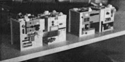 ABOVE: Building the interior frame detailing with plastic sheet and kit parts. BELOW: The detailed boxes in position within the frame. 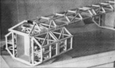
|
The interior detailing inside the framework could now be built. These box structures were made from 2mm plasticard and covered with lots of assorted kit parts. The actual detailing on the original models changed constantly, so it's impossible to be accurate. Besides, on the studio model, some of it was pretty awful and not good enough for a display model. As a result, I just had a bit of fun packing the areas with as much detail as I wanted. There is actually a recognisable kit part on the studio model which is a small Lunar Module from an Airfix Saturn V, which is glued on the top behind the nosecone. As I wanted my model to be as accurate as possible, I also glued this piece into position, but then I had to modify it because it's so blatantly obvious - I just couldn't stand to leave it there! Once I was happy with these sections, I sprayed them with grey primer and then dusted them with white primer until they just had a dirty, off-white appearance. These sections were then taken apart and re-assembled inside the frame. SIDE PODS: On the original model these four side pods were constructed from wood and covered with thin perspex sheets. In fact when you examine photos of the EAGLE, many of the lines on these sections aren't drawn-on panel lines but are the join lines where the perspex sheets overlap. Over the years these sheets of perspex are coming apart from the wood, due the action of various glues, paints or whatever. I decided to build mine differently and constructed each from 4mm thick perspex which was then 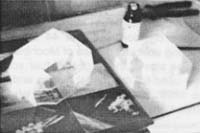 ABOVE: Creating the side pods with acrylic sheet and plasticard. BELOW: One of the nearly completed side pods with added kit details. 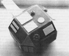 strengthened internally with the addition of resin and filler. A hollow central chamber was also created for the landing leg assemblies. The outer panel detailing consisted of 0.75mm plasticard and kit parts. The small attitude thrusters were actually made from the tips of plastic kit missiles which were hollowed out and glued into small cubes made from plasticard. The cubes were filled with putty, then the thrusters were drilled out completely. UNDERCARRIAGE: The four landing leg assemblies were agin fashioned from brass sections soldered together. The biggest problem here was being totally inaccurate with the shape and with the equal desire that they should all work properly. After a lot of thought, I had a definite idea of how far down the model should rest on its legs and how far those legs should unfold when the model is picked up. As a result, I built those limits into the legs' construction, so although the internal springs do move the legs and give a |
|
|

|
|