 ABOVE: Brass and perspex were used for making the landing legs. BELOW: The set of components for constructing just one landing leg. 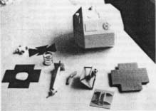 good feeling of cushioned suspension, they do not actually support the full weight of the model. In other words, I can't drop it because it will not bounce! The feet were hacksawed from thick perspex sheet and shaped on a belt sander. The small faint panels on the top edges are really self- adhesive paper labels that are just stuck on and sprayed over with light grey primer. Also of note, the main leg support isn't painted silver. It's actually thin aluminum tube disguising the brass pipe underneath. I've been warned that the aluminum surface cuts up after a while, hindering the legs' movement, so it's replaceable. NOSECONE: I have to admit that I cheated here and just used a casting that was allegedly taken from on original moulding, so there's not much to say on the subject. I still had to make all the outer cladding by heating pieces of 0.75mm plasticard and pulling them over the required spots. The pieces were then carefully cut out and superglued into position. The two window BELOW: The nosecone comes together. Note the turned aluminum engine bells. 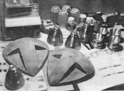
|
areas had to be carefully drilled out and a detailed interior was fabricated from plasticard, although much of the detail was drawn or painted on. As usual, the full sized set doesn't match the model cockpit, so it can't be built completely, but I did make a pair of reasonably accurate astronauts by modifying two 1/24 scale racing drivers. All this effort did seem rather wasted however, because when all this fantastic detailing is packed into the nosecone, you can't see any of it as the windows are so small. In fact, it's so dark in there I could have glued Nigel Mansell and Alain Prost in the seats without bothering to modify them! 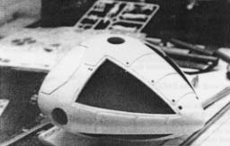 ABOVE: The nearly completed nosecone with added panel detailing. BELOW: Nigel Mansell and Alain Prost await their inclusion in the cockpit! 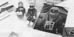 ENGINES: The engine assembly assembly was built as a separate unit that just plugged into the end of the framework, but it kept working loose, so I've since glued it in place. The construction is basically a central brass frame with a cluster of EMA domes and sections of plastic tube attached together with the four aluminum engine bells. These aluminum pieces were supplied by fellow model maker (although I've never seen him finish a model yet) Chris "Eagle" Trice who also produced copies of some old kit parts in resin, helped with the nosecone and made the Alpha waterslide transfers - thanks mate! The design of the engine section was changed for the second series because the model was outfitted with extra pipework to supply freon gas to the engine bells, creating the exhaust effect. I copied some of this design because I liked the extra pipework and I even considered trying to make the exhaust effect work on my model, but I decided against it. (As a point of interest, I thought that the gas somehow came straight through the centre of the engines, but it is in fact from the sides via the ring pipe that loops around the base of the engine bells.)  ABOVE: The basic shape of the EAGLE is well on its way to being completed. |
|
|

|
|